English
 русский
 Español
 Français
 Deutsch
 عربى
عربى



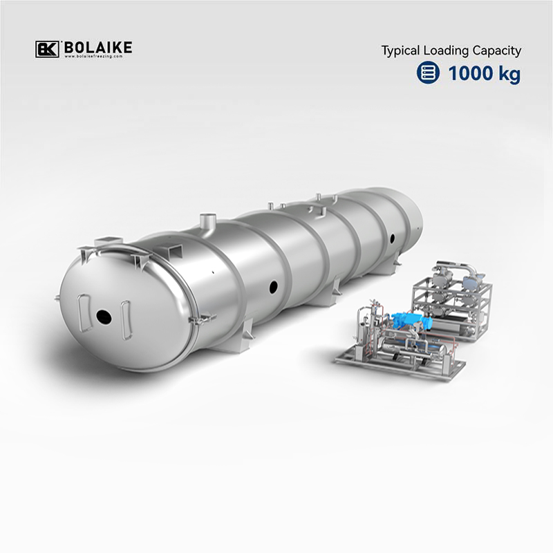
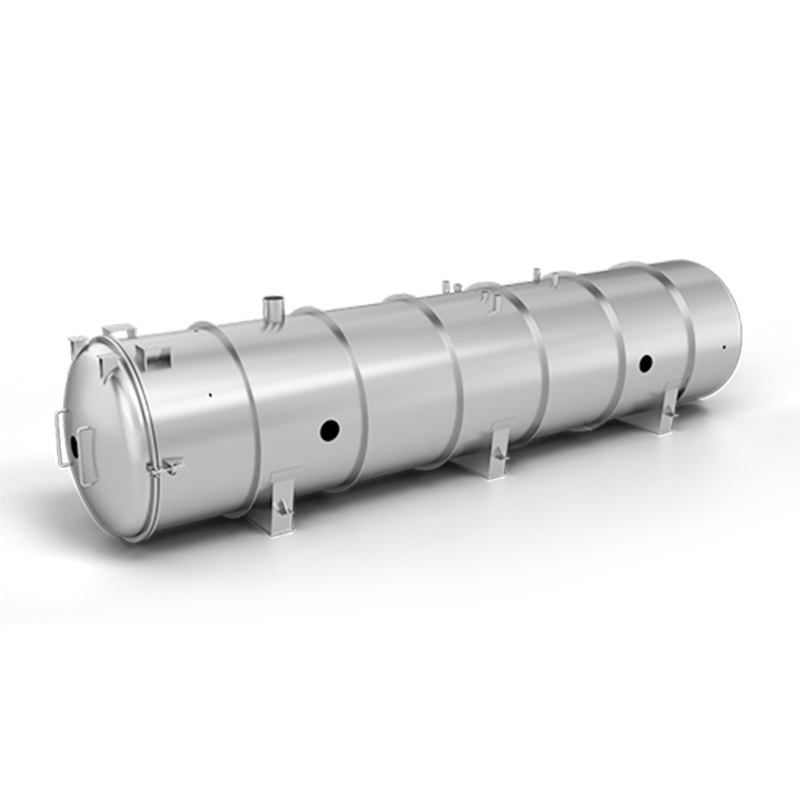
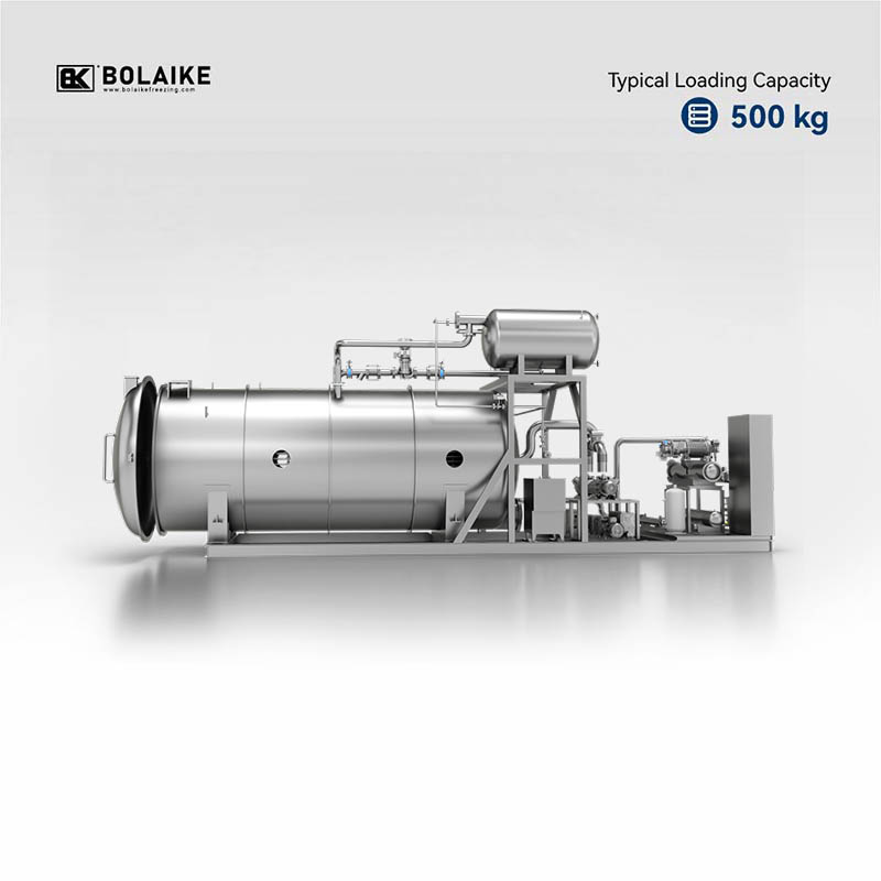
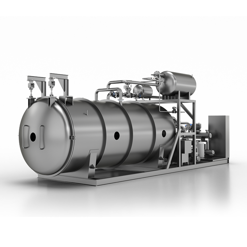




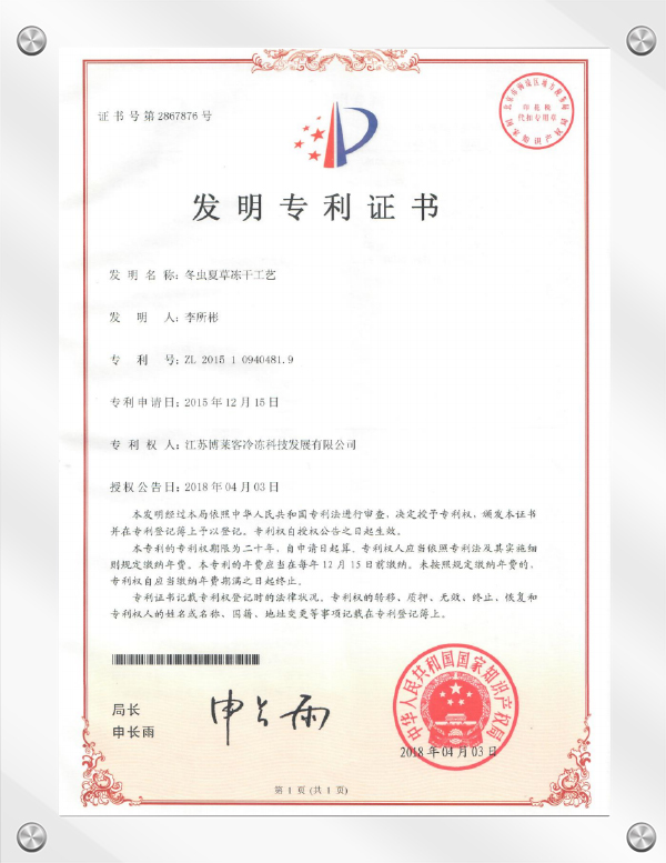
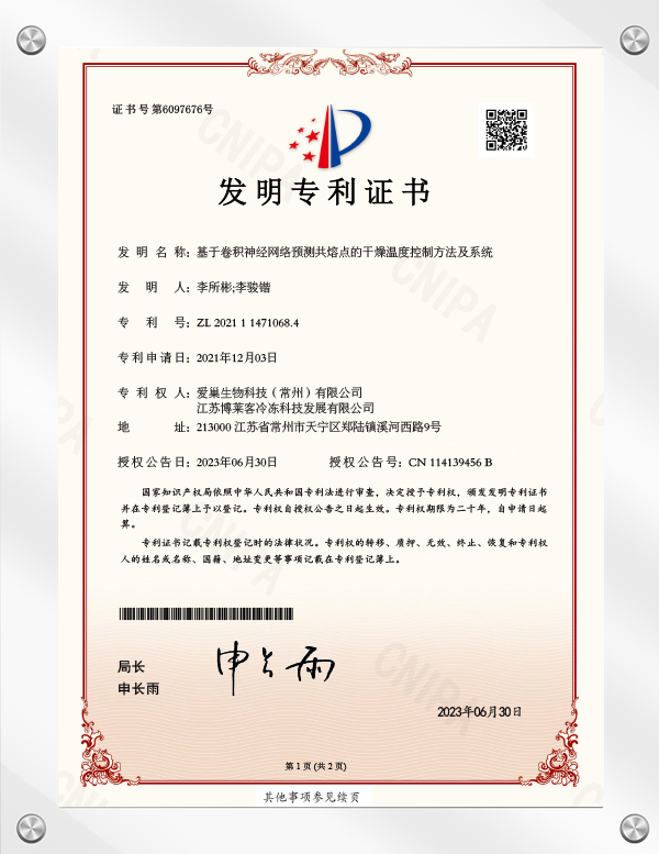


How Industrial Vacuum Freeze Dryers Prevent the Loss of an Entire Batch Due to Micro-Leaks
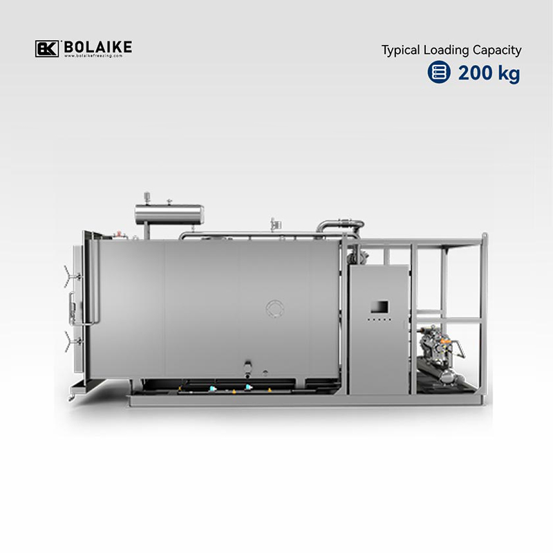
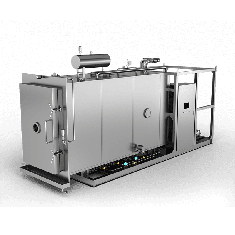
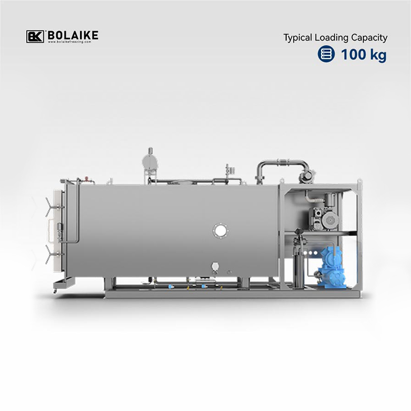
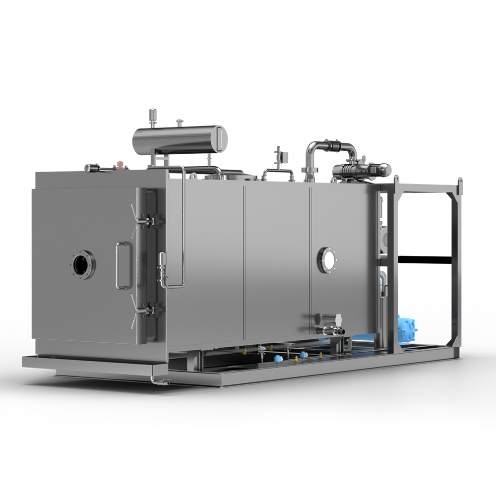
Vacuum freeze-drying, or lyophilization, is a critical preservation technology widely used in pharmaceuticals, biotechnology, food processing, and advanced material manufacturing. In industrial applications, a single freeze-drying cycle often processes high-value materials worth hundreds of thousands of dollars. The entire environment inside the drying chamber relies on precise pressure control, thermal dynamics, and stable vacuum thresholds to facilitate ice sublimation. However, micro-leaks—tiny fractures, seal imperfections, or microscopic fissures in pipe fittings—pose a severe threat to process stability. Even a minuscule leak rate can cause slow pressure degradation, leading to premature melt-back, collapse of the material matrix, or structural degradation. Preventing total batch failure caused by microscopic vacuum leaks requires a comprehensive approach integrating robust engineering, real-time diagnostic systems, advanced structural design, and proactive maintenance protocols developed by seasoned manufacturers like Jiangsu Bolaike Freezing Technology Development Co., Ltd.
The Risk Mechanism of Micro-Leaks during Lyophilization
Micro-leaks alter the internal thermodynamic state of the vacuum chamber during the primary and secondary drying stages. Sublimation occurs when heat is supplied to frozen material under a pressure below the triple point of water. If micro-leaks allow ambient air, moisture, or non-condensable gases to breach the chamber, the partial pressure of water vapor shifts dynamically. This pressure rise impedes the movement of vapor toward the cold trap condenser, causing heat to accumulate on the material shelves faster than the vapor can escape. As a result, the temperature of the frozen product may cross its collapse or eutectic threshold, triggering liquefaction or structural collapse. Once a batch undergoes collapse or melt-back, the original pore structure is permanently destroyed, rendering the product unrecoverable and leading to complete financial and operational losses.
Precision Chamber Architecture and Welded Structural Integrity
The primary line of defense against vacuum leaks lies in structural engineering and metallurgical execution. Industrial vacuum freeze dryers utilize high-grade stainless steel, typically AISI 316L for product-contact surfaces and AISI 304 for external jackets, designed to withstand deep vacuum stresses without mechanical deflection. Chamber joints and nozzle connections are constructed using automated orbital TIG welding to minimize micro-porosity within weld seams. Internal surfaces undergo precision mechanical grinding followed by electropolishing to achieve smooth surface finishes, often with a roughness average below 0.4 micrometers. This mechanical refinement removes microscopic pits and micro-fissures where gas molecules can collect or where stress cracks could form over repeated thermal cycling. The underlying structural framework engineered by Jiangsu Bolaike Freezing Technology Development Co., Ltd. focuses on reducing mechanical connection points, replacing threaded joints with hygienic tri-clamp or flanged connections featuring specialized elastomeric seals to systematically eliminate potential leak paths.
Advanced Gasket Materials and Dynamic Seal Design
Sealing interfaces around chamber doors, ducting, and movable shelf penetrations represent primary areas prone to micro-leakage. Standard elastomeric materials degrade over time under continuous thermal cycling, exposure to aggressive cleaning chemicals, or prolonged vacuum exposure, leading to micro-cracking and loss of elasticity. Industrial freeze dryers employ specialized synthetic elastomers such as cured silicone, EPDM, or fluoroelastomers like Viton, chosen for their low outgassing properties, compression set resistance, and stability across extreme temperature ranges from below minus 50 degrees Celsius to above 120 degrees Celsius. In addition, door seals often feature dual-lip or inflatable gasket profiles that maintain consistent seating pressure against the sealing face regardless of thermal expansion or pressure differentials across the chamber boundary.
| Seal Type | Temperature Range | Chemical Resistance | Primary Application Area |
| Cured Silicone | -60°C to +200°C | Moderate steam resistance, low outgassing | Main chamber door gaskets and observation ports |
| EPDM Fluorocarbon | -45°C to +150°C | High resistance to CIP chemicals and clean steam | Internal fluid lines, valve seats, and sanitary unions |
| Fluoroelastomer (Viton) | -20°C to +200°C | Exceptional chemical and solvent resistance | High-vacuum seals, pump connections, and isolation valves |
Pressure Rise Testing and In-Line Leak Detection
To verify vacuum integrity prior to loading high-value inventory, automated pressure rise testing, also known as pressure decay or rise rate testing, is integrated into the pre-cycle qualification sequence. After evacuating the empty chamber to baseline vacuum, all isolation valves are closed to isolate the drying vessel. The control system continuously monitors the pressure increase over a defined time interval. A pressure rise rate exceeding established thresholds (typically measured in millibar-liters per second) signals a micro-leak or outgassing issue, triggering an alarm that halts cycle execution before valuable material is introduced into the chamber.
| Test Method | Sensitivity Level | Operational Timing | Primary Diagnostic Function |
| Automated Pressure Rise Test | 10^-2 to 10^-3 mbar·L/s | Pre-cycle qualification / Post-CIP-SIP | Verifies overall chamber isolation integrity |
| Helium Mass Spectrometry | 10^-7 to 10^-9 mbar·L/s | Factory acceptance & routine maintenance | Pinpoints exact location of microscopic cracks or flange leaks |
| Continuous Capacitance Manometry | Real-time tracking | Active drying phase monitoring | Detects abnormal pressure drift caused by sudden seal failure |
Dual-Sensor Vacuum Monitoring and Comparative Diagnostics
Single-sensor pressure monitoring can mask micro-leaks or fail to distinguish between water vapor sublimation and true ambient air ingress. Modern industrial freeze drying systems implement dual-sensor technology combining a Pirani thermal conductivity gauge with a capacitance manometer (Baratron). The Pirani gauge reading depends on the thermal conductivity of the gas composition inside the chamber, while the capacitance manometer measures absolute force/pressure independent of gas type. During normal sublimation, the atmosphere consists almost entirely of water vapor, causing a characteristic discrepancy between the two gauge readings. If a micro-leak allows ambient air (nitrogen and oxygen) to enter, the ratio between the Pirani and capacitance readings shifts predictably. Automated control systems analyze this sensor offset in real time to differentiate between normal moisture release and external air leakage, enabling early intervention before product degradation occurs.
Redundant Vacuum Line Architecture and Automatic Isolation Controls
Mitigating the impact of micro-leaks also depends on rapid system containment and process redundancy. Industrial lyophilizers utilize dual-stage vacuum pump groups featuring combination rotary vane, dry screw, or Roots blower pumps operating in parallel or series configurations. If a localized seal leak occurs along a vacuum line or auxiliary valve, automated pneumatic isolation valves isolate the compromised branch without losing system vacuum altogether. Auxiliary booster pumps dynamically engage to handle the additional gas load, maintaining internal chamber pressure within the specified tolerance band. This automated redundancy buys critical time for process operators to complete the current phase safely or implement controlled batch protection sequences, shielding the inventory from catastrophic loss.
FAQ
Q: How do industrial vacuum freeze dryers handle the challenge of non-uniform heating across large shelf surface areas?A: Thermal uniformity across large production shelves relies on engineered fluid distribution circuits rather than direct electric heating. Heat transfer fluids, such as silicone oil or thermal fluids, are pumped through internal flow channels embedded within every shelf plate. System designs developed by experienced manufacturers like Jiangsu Bolaike Freezing Technology Development Co., Ltd. utilize multi-inlet headers and turbulent flow configurations. This ensures fluid temperature variation across the entire shelf array remains tightly contained, preventing localized hotspotting or under-drying during sensitive primary sublimation phases.
Q: Why is dual-sensor vacuum measurement essential for detecting the true completion of primary drying in an industrial freeze dryer?A: Using a single pressure gauge can result in inaccurate cycle timing, as individual sensors measure pressure differently depending on gas composition. Industrial systems pair a Pirani thermal conductivity gauge with a capacitance manometer. Because water vapor and non-condensable room gases conduct heat at different rates, the Pirani gauge reads artificially higher during active sublimation when water vapor dominates the chamber. As sublimation nears completion and water vapor drops, the Pirani reading converges with the absolute pressure reading of the capacitance manometer, giving operators a precise physical indicator that primary drying is complete without opening the chamber.
Q: What design features prevent moisture bypass from reaching vacuum pump groups during heavy sublimation loads?A: High vapor generation during peak sublimation can overload standard vacuum pumps if moisture bypasses the cold trap. To protect pump mechanics and maintain deep vacuum, industrial freeze dryers feature strategically positioned condenser coils or internal vapor baffles cooled to sub-zero thresholds (often below minus 50 degrees Celsius). Smooth gas duct geometries direct the expanding vapor stream directly over high-surface-area cold plates, freezing out water vapor before air reaches the vacuum pump inlet. This prevents pump oil contamination, vapor lock, and sudden loss of process vacuum.
Q: How do Clean-in-Place (CIP) and Sterilize-in-Place (SIP) systems maintain hygiene without damaging sensitive vacuum sensors and seals?A: Automated CIP/SIP protocols utilize targeted spray nozzle grids, high-pressure washing loops, and pure steam injection reaching temperatures above 121 degrees Celsius. To prevent seal degradation or gauge drift from extreme thermal and moisture exposure, vulnerable instruments are shielded behind automated pneumatic isolation valves that close before the cleaning or steam cycle initiates. Furthermore, sanitary elastomeric gaskets like EPDM or fluoroelastomers are rated specifically for steam resistance, ensuring mechanical seals hold structural shape across rapid cooling and heating cycles.
Q: What techniques are used to optimize total energy consumption during 24- to 72-hour continuous production cycles?A: Energy management in large-scale processing focuses on demand-based compressor staging and thermal energy recovery. Rather than operating refrigeration compressors at maximum capacity throughout the entire cycle, multi-stage screw or scroll compressors utilize frequency converters to match power draw with actual cooling demand. Heat rejected from the refrigeration condensers is often reclaimed to pre-heat the thermal fluid circuit for shelf warming during secondary drying, significantly cutting overall electrical utility consumption across extended drying runs.